In the Autocad rar I have included drawings for each part as well as a 3d model in dwg. Motor is open dripproof ODP for use in clean dry and well-ventilated environments.

Gear Pump Assembly Drawing Machine Drawing Learn To Draw With In 5 Min Youtube
The pump is so named because it has two gears that are side-by-side or externalto each other.
. A step by step sequence followed is attached as a document you. External gear pumps which use two external spur gears and internal gear pumps which use an external. 09723599 Quantity 1ST L 1ST L Item Order No.
34 28 Body Width Item No. Disassembly of a Triple Pump During disassembly keep all mating part in order and together. After cleaning remove port plugs and drain oil.
Pumps are gravity fed and require an elevated liquid source to fully fill the pump before turning. 09438467 09650747 A-A Denomination INTERNAL GEAR PUMP ASSEMBLY WEAR PLATE. 26 45 cm3r in3r Body Assembly mm in.
The original design is from a book for mechanical design. Sectional elevation through longitudinal axis of driving shaft showing an assembled pump. 2 Put a location mark across front plate body and backplate to assure proper reassembly.
There are two main variations. This video make by Vishwakarma Engineering Drawing Classes Bhilai Nagar. Designation Quantity 1 R909439861 PUMP COVER 1 ST 2 R909415375 STUB SHAFT 1 ST 3 R909449134 BEARING BUSHING 1 ST 7 R902006253 WHEEL SET 1 ST 8 R902025647 SHAFT KEY 1 ST 9 R909156741 SNAP RING 1 ST.
A gear drawing is a type of important technical reference required when designing machines. Pump Parts Drawing Triple righthand CW rotation pump shown. Thoroughly clean the outside of the pump.
Spare parts list Order No. Disassembly 1 Remove key from drive shaft if keyed drive gear assembly is used. I COVER CI PULLEY CI GLAND CI GLAND BUSHING Bronze GEAR BUSHING Bronze DRIVING GEAR 7T 6P Steel from STEP file of Creo Involute Gear DRIVEN GEAR 7T 6P Steel from STEP file of Creo Involute Gear.
This paper presents a model for gear pump assembly design realized in Solid Edge V20. BCH 9000 from 45 to 90 ccrev. 1 shows a simplified drawing of an external teeth gear pump on the left along with the alternate arrangement of internally pointing teeth.
BCH 9000 from 15 to 30 ccrev. BCH 9000 from 45 to 9 ccrev. Gear pump assembly drawing.
Also known as gear pumps these produce a smooth flow of liquid to lubricate equipment and blend oils. 3 Series 26 - Model 26000 Multiple Gear Pump Pump Parts List Displacement Item No. A high-horsepower motor moves oil with a viscosity similar to SAE 60 motor oil.
A simple gear pump. INTERNAL GEAR PUMP ASSEMBLY engineering mannesmann Rexroth Brueninghaus Hydromatik Elchingen Plant Type. Gear pumps are also widely used in chemical installations to pump high viscosity fluids.
Pump assembly from vehicle and plugging ports. When a machine designer requires a gear when designing a new machine there are two possibilities. Is to highlight modelling aspects for solid part components and how to.
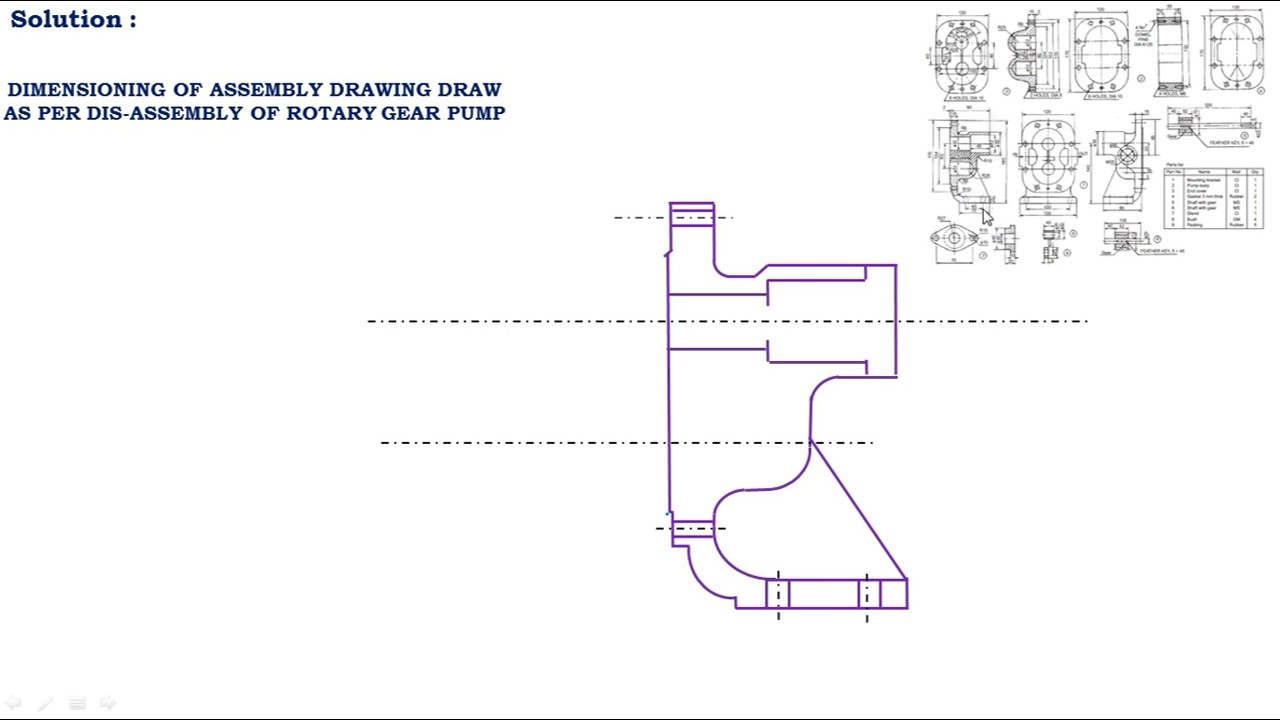
Let see the Basics of Gear Pump first. This drawing provides useful information for assembling the machine as this drawing reveals all parts of a machine in their correct working position. 67 29 Item No.
Designing the new gear itself and utilizing a standard gear which has already been designed. External and Internal Teeth Gear Pumps. Thoroughly clean the outside of pump.
Glockeraustraße 2 D-89275 Elchingen. 1234 Installation Assembly Drawing. 0 In order to download this file you should sign up and make a contribution.
1 Remove key from drive shaft if keyed drive gear assembly is used. On this drawing the location and dimensions of few important parts and overall dimensions of the assembled unit are indicated. Also include a bill of material.
Manolis TheofilosJuly 22nd 2011. 44 49 Item No. Russian HydraulicsPneumatics Compass Educational Added.
Hydro-gear a world leader in turf care transmission products. 2 P a g e From the assembly drawing shown above create the following parts for Rotary Geared Pump assembly. ResearchGate Gear pumps fall under the category of positive displacement pumps rotary pumps.
E N G I N E E R I N G - Gear Pump Basics The external gear pump is a positive displacement PD type of pump generally used for the transfer and metering of liquids. 2 Put a location mark across front plate bodies adapters. Up to 5 cash back Draw the following assembled views of gear pump.
End view one half of outside view looking on gland with coupling removed the other half a section through the pump casing looking at the ends of the pinions. A gear pump uses the meshing of gears to pump fluid by displacement. INTERNAL GEAR PUMP ASSEMBLY Mobile Hydraulics Product Unit Axial Piston Units Drawing no.
BCH 9000 from 005 to 24 ccrev. Bdp-10l variable pump variation chart. They are one of the most common types of pumps for hydraulic fluid power applications.
To disassemble or assemble a double pump the center assembly shown here will be eliminated. In general gear pump encloses a fixed volume of fluid by the help of interlocking cogs or by meshing of gears and applies mechanical force pressure energy on that entrapped volume. Pump assembly from vehicle and plugging ports.
Disassembly procedures for variable pump reconditioning and replacement of parts assembly procedures for variable pump parts drawing parts list. A Upon leaving the offset plate the impeller blade straightens and creates a vacuum drawing in liquidinstantly priming the pump b As the impeller rotates it carries the liquid through the pump from the intake to outlet port each successive blade drawing in liquid c When the flexible blades again contact the offset plate they bend with a squeezing action. After cleaning remove port plugs and drain oil.
Here you can learn to draw an assembly drawing of a Gear pump in just 5 min. This nomenclature differen-tiates it from an internalgear pump which has one gear. 3 Clamp pump in vise shaft end up.
In either case the gear drawing is indispensible. A gear pump uses two meshing toothed cogs to force water from the inlet of the pump through to the outlet.

Drawing Of Gear Pump Used In The Ried Test To Explore Undergraduate Download Scientific Diagram

Internal Gear Pump Assembly Spare Parts In A10vg45da1d2 10r Nsc10f013sh Mh Hydraulics

Solidworks Drawing Tutorial Gear Pump All Drawings In One Sheet Youtube

The Gear Pump Assembly In A 3d Exploded View Download Scientific Diagram
/23311.jpg)
New Holland 4400v 2 Section 011 Gear Pump Assembly

Gear Pump Assembly 29 Download Scientific Diagram

Gear Pump Exploded Exploded View Drawing Wikipedia The Free Encyclopedia Hydraulic Systems Gear Pump Hydraulic Pump
Assembly Drawing Of Rotary Gear Pump Youtube
0 comments
Post a Comment